Plastic Pvc Pipe Fittings,Pvc Plastic Water Pipe,Plastic Pipe Tube,Plastic Rounded Tube Dandong Jinggong Heat Preservation Appliance Factory , https://www.jgplastic.com
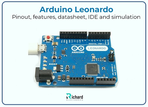
Arduino Leonardo is a versatile and powerful microcontroller board that stands out for its ability to emulate a mouse or keyboard without requiring additional libraries. It features 20 digital I/O pins, 7 of which support PWM output, and 12 analog input pins. Additionally, it supports communication protocols such as UART, SPI, and I2C. Let's explore its history, pinout, datasheet, features, IDE, and simulation.
### History of Arduino Leonardo (A000057):
- In 2012, Arduino Leonardo was released in the Arduino series to expand the family of Arduino microcontroller boards.
- Based on the ATmega32u4, it includes native USB support.
- It was the first Arduino board with native USB communication, excluding the need for a separate USB-to-serial adapter.
- Designed for advanced projects where direct interaction with a computer via a USB port is required.
- Fully supported by the Arduino IDE, making it easy to program.
- Features USB HID capability, distinguishing it from previous Arduino boards.
- Widely used in professional prototyping and educational environments due to its versatility and unique features.
### Pinout of Arduino Leonardo:
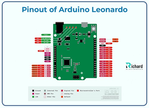
#### Digital Pins:
- D0-D13: These are general-purpose digital I/O pins. D0 and D1 are used for serial communication (RX and TX), while others can be used for various purposes.
- PWM Output: Pins 3, 5, 6, 9, 10, and 11 support PWM output.
| Number of pins | Type of pin | Name of pins/ protocol | Detail |
|----------------|---------------------|------------------------|--------|
| D0 | Serial or digital I/O pin | RX (UART) | Used for serial communication receive signals (UART) |
| D1 | Serial or digital I/O pin | TX (UART) | Used for serial communication transmit signals (UART) |
| D2 | Interrupt or digital I/O pin | Digital pin | Used for INT2 (External interrupt) or digital output or input |
| D3 | Interrupt, digital I/O pin or PWM pin | PWM pins | Used for INT3 (external interrupt) or pulse width modulation output |
| D4 | Digital I/O pin | Digital pin | Used for all-purpose input or output pin |
| D5 | PWM or Digital I/O pin | PWM pin | Pulse width modulation output pin |
| D6 | PWM or Digital I/O pin | PWM pin | Pulse width modulation output pin |
| D7 | Digital I/O pin | Digital pin | Used for all-purpose input or output pin |
| D8 | Digital I/O pin | Digital pin | Used for all-purpose input or output pin |
| D9 | PWM or Digital I/O pin | PWM pin | Pulse width modulation output pin |
| D10 | PWM, Digital I/O pin, and SPI | PWM pin | Pulse width modulation output pin or SPI (SS) |
| D11 | PWM, Digital I/O pin, and SPI | PWM pin | Pulse width modulation output pin or MOSI |
| D12 | SPI or digital I/O pin | Digital pin | For all-purpose digital pin or MOSI |
| D13 | LED or Digital I/O pin | LED pin | Pin 13 connected with onboard LED |
#### Power Pins:
| Name of pins | Protocol/ type of pin | Detail |
|--------------|------------------------|--------|
| GND | Ground pin | Ground pins are used to complete the circuits. |
| 5V | Power supply output pin | 5V power supply regulated through USB and also used for external power supply |
| RESET | Reset pin | Used to reset the microcontroller board. |
| VIN | Power supply input pin | Used for input voltage 7V - 12V. |
| AREF | Analog reference pin | Used for reference voltages |
| 3.3V | Power supply output pin | The power supply of 3.3V regulated through this pin |
#### Specific Pins:
- **Interrupt pin**: Used for external interrupts.
- **Pin 13**: Built-in LED.
- **SPI**: This pin is used for SPI communication and is present on ICSP headers which are MOSI, SCK, and MISO.
- **I2C pins**: Data line or clock line, pin 2 or pin 3 used for I2C communication.
| Name of pin/ header | Protocol/ type of pin | detail |
|---------------------|------------------------|--------|
| Native USB support | USB communication | It supports the native USB or is used in HID projects as a mouse, keyboards |
| ICSP headers | SPI communication | For serial peripheral devices, the SPI interface is used. |
#### Analog Input Pins:
With 10-bit resolution, these pins are used to read or scan the analog inputs between 0V - 5V.
| Name of pin | Number of pins | Type of pin | detail |
|-------------|----------------|---------------------|--------|
| Analog input pin | A0 | Analog input pin | Used as a digital I/O pin, or the analog input pin |
| Analog input pin | A1 | Analog input pin | Used as a digital I/O pin, or the analog input pin |
| Analog input pin | A2 | Analog input pin | Used as a digital I/O pin, or the analog input pin |
| Analog input pin | A3 | Analog input pin | Used as a digital I/O pin, or the analog input pin |
| Data line (SDA) | A4 | I2C communication or analog input pin | Used as a digital I/O pin, analog input pin, or for I2C communication |
| Clock line (SCL) | A5 | I2C communication or analog input pin | Used as a digital I/O pin, analog input pin, or for I2C communication |
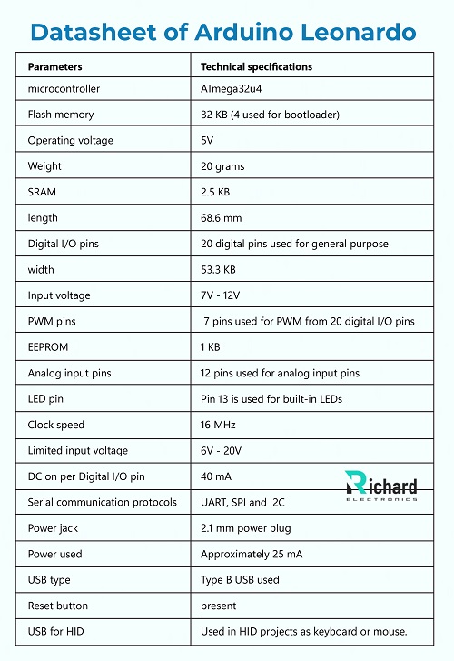
### Datasheet of Arduino Leonardo:
Technical specifications are crucial to understand the capabilities and unique features of the board. You can download the Arduino Leonardo datasheet by clicking the button below:
[Download Arduino Leonardo Datasheet](#)
Here are some of its important features:
| Parameters | Technical specifications |
|------------|--------------------------|
| Microcontroller | ATmega32u4 |
| Flash memory | 32 KB (4 used for bootloader) |
| Operating voltage | 5V |
| Weight | 20 grams |
| SRAM | 2.5 KB |
| Length | 68.6 mm |
| Digital I/O pins | 20 digital pins used for general purpose |
| Width | 53.3 mm |
| Input voltage | 7V - 12V |
| PWM pins | 7 pins used for PWM from 20 digital I/O pins |
| EEPROM | 1 KB |
| Analog input pins | 12 pins used for analog input pins |
| LED pin | Pin 13 is used for built-in LEDs |