We focus on 3ton to 20 ton Truck Crane for 20 years. Main products include: truck crane, Crane Truck , Mobile Crane, Truck Mounted Crane, car mounted crane, self-make crane and Tractor Crane.
Company insists on the quality management policy of [Quality First, Honest Operation, Scientific Management, and Continuous Improvement," defines the quality management objective, keeps to the quality assurance and provides high-quality products and services for customers. Our sales network spreads over 30 provinces and cities in domestic market, and products are exported to over 30 countries and regions like Argentina, India, Mauritius, Malaysia, Iran and Bhutan, and are deeply trusted and well received by domestic and foreign users.
Small Crane,Small Overhead Crane,Small Manual Crane,Small Car Cranes Jining Sitong Construction Machinery Co.,Ltd , http://www.cntruckcrane.com
Inductive power meters and ordinary electronic power meters have many drawbacks, such as a single function, poor anti-electricity protection, backward meter reading, and IC card damage, in order to adapt to the trend of smart meter. The application of radio frequency identification (RFID) technology to the transmission of electricity information to better reflect the advantages of RFID contactless, passive, and information security. Radio frequency identification technology is a kind of non-contact automatic identification technology. It uses white light to identify the target object and obtain relevant data. The basic RFID system is composed of two parts: electronic mark (RF card), reader and application support hardware and software. The RFTD tag consists of a chip and an antenna, and each tag has a unique electronic code. According to the way to send radio frequency signals. Labels are divided into active and passive two types of active tags. The built-in battery provides active transmission of RF signals to readers. After receiving the electromagnetic wave signal from the reader, the passive tag converts part of the electromagnetic energy into energy for its own operation and responds accordingly. The reader is responsible for transmitting the read signal to the tag and accepting the response of the tag. Liu tag's object identification information is decoded, and the related information of the object identification information and associated tags is transmitted to the host for processing. The RFID application support software and hardware is mainly responsible for implementing the functions related to the enterprise = or organization application.
1, working principle
The electric energy meter star chip produces the electric energy pulse signal and the electric current direction signal according to the voltage, electric current input signal and sends to the MCU for processing. The MCU accumulates the charge pulses. The electricity is calculated and stored. At the same time, the remaining electricity blue is subtracted according to the current rate, and whether or not to alarm or power off is determined. The MCU continuously reads the clock and determines the current operating rate. The MCU also monitors the RS485 bus and infrared communication signals and receives or responds to commands for serial communication. In addition, the meter also monitors relay status and battery voltage, power, and other parameters, and alerts and records non-nI:normal status.
An RFID-based single-phase electronic energy meter hardware circuit includes an energy metering unit, a radio frequency interface unit, a communication unit, a storage unit, a clock unit, a display unit, a keyboard processing unit, a load control unit, an MCU monitoring unit, and a direct current Power unit and other parts. Intelligent power meter block diagram shown in Figure 1.
The microcontroller uses TI's ultra-low-power microcontroller MSP 430F427, which has 16k BFLASH and 1kBRAM, comes with a 128-segment LCD driver. The metering part uses ADI's dedicated electric energy metering sheet ADE7755. The radio frequency reads and writes the interface chip to select the PHILIPS company reader special-purpose chip MFRC500, the radio frequency card uses the low-cost passive type Mafare MF1 card. The storage part uses E-PROM memory AT24LC16 and the real-time clock adopts the DS3231 of MAXIM with automatic temperature compensation. The lithium battery is used to ensure that the n1 of the energy meter is always running when the power grid is cut off. The power-down monitoring unit uses the MAX705 to monitor the operation of the linear power network in real time. The load control part adopts the BST-902-(50) type A magnetic latching relay of Shanghai Best Company to control the on-off of the load. The information exchange of the electric energy meter and the buccal machine adopts near-infrared photoelectric communication and a remote HS485 bus. The energy meter uses buttons to query critical information. 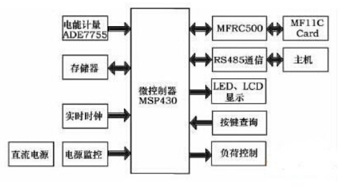
2, hardware design
2.1 Energy metering The ADE7755 uses a mixed-circuit design. The analog part includes two 16-bit sigma-delta analog-to-digital converters (ADCs) and a reference circuit. The digital part is also called a digital signal processing module, which includes a phase corrector and a high-pass filter. , multipliers, low-pass filters, digital-to-digital converters, etc. The hybrid circuit design combines the advantages of analog and digital circuits. The high-precision 16-bit sigma-delta ADC guarantees the linearity and accuracy of the signal; phase correction, filtering, multiplication, and digital-to-digital conversion in the digital domain are beneficial for improving the operation. The stability of the result. Therefore, the ADE7755 chip has high stability and accuracy even if it is operated in an extremely harsh environment for a long time, and its accuracy exceeds the requirements of the IEC61036 standard.
The ADE7755's metering circuit is shown in Figure 2. The voltage is connected to the voltage measurement channel sampled by the ADE7755 through the resistor divider network. The current passes through the manganese copper sheet and is sent to the current measurement channel of the ADE7755. The linearity of the ADE7755 is 1 ‰, which ensures the measurement accuracy. The CF frequency output is connected to the IO port of the MCU via an external filter circuit. The ADE7755 sets a minimum output frequency. When the output frequency produced by the load is lower than the specified minimum output frequency, F1, F2, and CF will not output any pulses. This frequency is 0.0014 for the F1-4 corresponding to the full-scale output frequency. %. The pulse constant of the electric energy meter is 1600imp/kWh, the maximum load current is 40A, the most suitable F1-4 frequency is 13.6Hz, namely S0=1, S1=1, SCF=0. 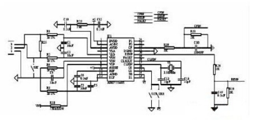
2.2 RF Interface Section The MFRC500 is a member of the highly integrated IC series for 13.56 MHz non-contact communication. The IC series utilizes advanced modulation and demodulation concepts and fully integrates all types of passive contactless communication methods and protocols at 13.56 MHz. The MFRC500 supports all layers of the IS014443A. The internal transmitter section can directly drive near-operating distance antennas (up to 100mm) without the need for additional active circuitry, and the receiver section provides a robust and efficient demodulation and decoding circuit for ISO14443A compliant transponder signals. The digital part handles ISO14443A frame and error detection (parity and CRC). In addition, it also supports the fast CRYPTOI encryption algorithm for verifying Ml team RE series products. The convenient parallel interface can be directly connected to any 8-bit microprocessor, which provides great flexibility for the design of the reader terminal and is particularly suitable for applications in three watches.
RFID is a tool for prepayment of electricity meters. With RFID technology, we can easily realize the prepayment of electricity meters. Use the MFRC500 chip for reading and devaluation in RFID. Because the bus of the one-chip computer does not expand outside, can't operate MFRC500 directly as the external memory. In this regard, the author uses an analog bus to communicate with the MFRC500. Figure 3 shows the connection diagram of the MFRC500 chip and the MSP43O. Here, the P6 port is connected to the DO-D7 of the MFRC500. Pl.6 connects READ, Pl.7 connects WRITE, Pl.4 connects ALE, P2.O connects RSTPD and so on. The antenna section uses the antenna recommended in the data sheet. 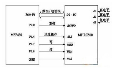
3.1 The main program flow Software is the soul of the meter. The energy meter needs to complete functions such as energy metering, rate and period control, query, display, electricity charge, load control, event recording, and test output. Power meter software design mainly uses C language, using modular programming ideas, including the following modules: power on initialization module, main program module, power accumulation module, data storage module, interrupt program module, LCD display module, key processing module , rate processing module, real-time clock processing module, radio frequency read-write module, communication event processing module, load control module, etc. The main program flow chart shown in Figure 4. 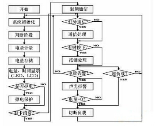
The main program checks whether the accumulated power consumption of the pulse interruption subroutine reaches a predetermined value (eg 0.1 kWh). Upon arrival, this value is credited to the unit of accumulated power usage. Because it is a multi-rate electricity meter, according to the real-time clock switching rate, according to the set different time periods, they are respectively stored in the peak power, flat power or valley power unit, and display the power and related data according to demand.
3.2 RF card reading and writing process The working distance between the Mifare card and the reader antenna is ≤10mm, the data transmission rate is 106kbit/s, and the time for completing a read/write can be less than 0.1s. The card has anti-collision function. The entire circuit (except the coil) is integrated in one chip. The MCU first initializes and configures the MFRC 500. After the register is set, the MFRC500 can receive commands from the MCU to perform operations and communicate with the Mifare card. The Mifare card can operate according to the received instructions. However, a single-chip microcomputer cannot read and write IC cards through simple instructions, and it requires a series of operations to complete communication. Mainly include: 1) Request to wake up; 2) Anti-overlap (prevent data errors caused by overlapping of multiple cards); 3) Select a card; 4) Password authentication; The series of operating procedures for the Mifare card must be performed in a fixed sequence. When a Mifare card enters the effective range of the RF antenna, the reader program will begin the above series of operations. In order to improve the processing and response speed, the program design uses a single-chip assembly language and C language mixed programming. The interrupt service routine is written in assembly language. Other programs are written in C language and call the basic library functions provided by PHILIPS to implement various functions.
4, anti-jamming design
Because the working environment of the electricity meter is very bad, the common interference sources are: transients and high-frequency pulses, low-frequency pulses, lightning, electromagnetic radiation, harmonics and flicker. As a very important measuring instrument, the power meter must ensure that the CPU runs normally within ten years without running, the data is not lost, the chip is not reset abnormally, and even if an exception occurs occasionally, the system must be able to recover from the failure in time. Therefore, careful reliability design must be performed from both hardware and software.
4.1 Hardware anti-jamming 1) Reduce the bandwidth and isolate the sensitive part of the system: If the power collection module collects the user's power from the power grid, the interference is very large, and it can be packaged separately with the power metering circuit and kept at a certain distance.
2) Using varistors: When the watt-hour meter is disturbed by transients, the varistor responds extremely quickly at the nanosecond speed, forming a low-resistance shunt during overvoltage, which can enhance the transient immunity of the watt-hour meter against power grids. The ability to impact.
3) Opto-isolation: The pulse signals generated by the ADE7755 are isolated by the opto-isolator and then collected by the SCM. This prevents the pulse interfering signals from entering the microcontroller.
4) Anti-jamming design of circuit board: 1 Analog circuit and digital circuit are separated; 2 Analog ground and digital ground are separated and single-point earthed; 3 PCB board is covered in large area; 4 CPU chip pins are not floating; 5 will have bigger interference chip Put away from the MCU and so on.
4.2 Software anti-jamming 1) Repeated key detection: Repeated detection is performed using the timer, the key is scanned at a frequency of 40 Hz, and only one button event is considered to have occurred only when the key interface is detected to be low for 3 consecutive times. In this way, a reliable and effective signal after debounce can be obtained, thereby avoiding the misoperation of the keys caused by the interference.
2) Instruction Redundancy: Instruction redundancy is the intentional insertion of some single-byte instructions or the rewriting of valid single-byte instructions at the critical points of the program. It is an effective measure to restore the program from the "flying" state. The prerequisite is that the PC pointer must point to the program operating area, and the redundant instructions must be executed.
3) Software traps: When the in-flight program enters a non-programmed area, a software trap is set, that is, a jump instruction is added to intercept the indiscriminate flight program, and it is quickly led to a specified position, and then the error processing is performed, so that the program is restarted. Get on track.
4) Program watchdog timer (watchdog): The watchdog monitors the running status of the program to determine whether the program enters an infinite loop or a program "runaway" phenomenon, thereby forcing the program to return to the reset state. The main program of the system is a loop structure, and a watchdog reset instruction is set on the loop path.
5. Concluding remarks
The development trend of the electric energy meter is high precision, multi-function and intelligence. Radio frequency identification technology has become a new force in information technology. The innovation of this article is reflected in:
1) The use of TI's 16-bit MSP430 microcontroller for power meter design, its ultra-low power performance to promote the "low-carbon economy";
2) RF card instead of contact IC card, long life, easy to use, data transmission security;
3) Multifunctional. The meter can achieve multi-rate, time-phased billing, prepayment, load control, near-infrared meter reading and remote RS485 bus meter reading, power-off protection and other functions.
introduction Figure 3 Connection between MFRC500 chip and MSP430 3, software design
Figure 1 power meter functional block diagram
Figure 2 energy metering circuit
Figure 4 main program flow chart