What engineers are most worried about in the field of industrial communications? Communication interference! The CAN isolation module can effectively solve the CAN bus communication interference problem and is easier to use than discrete device solutions. This article summarizes the details that need to be taken into account when using the CAN isolation module to help you build a more reliable CAN bus network.
“Isolation†is the primary guarantee for the module to provide reliable data transmission for the CAN node equipment. Usually “isolation†of the isolation module means that after the module is powered on, it can provide signal isolation and power isolation for the node. The isolation voltage level is mainly based on 2500VDC and 3500VDC. . This article will proceed from the four levels of the pre-stage power protection, post-stage grounding, bus protection circuit, and actual networking of the CAN isolation module, and introduce the details of the module in all aspects to help us build a stable and reliable CAN bus network.
1. Pre-power protection
The primary interface of the module is the part of the control signal. The power supply is usually consistent with the CAN controller or MCU. In this case, a 10μF filter capacitor is recommended for the power port. In some applications, the power supply of the module is transmitted together with the bus. For example, the power supply of each of the 20 nodes is wired together with the CAN signal line, the nodes share a single power supply, or the module does not have a separate regulated power supply. This must be a module. The power supply adds TVS protection and filter capacitors, and ensures that the power supply and the signal are common ground, as shown in Figure 1 below.
Figure 1 Power protection
2. After the grounding
Generally, the CANG of the CAN transceiver can be left unattended during short-distance and low-interference situations. However, in practical field applications, the vast majority of CAN bus networking adopts shielded twisted pairs. In this case, the shielding layer needs to be grounded. If the grounding node is a metal chassis and the primary system of the node is grounded, in this case, the shield of the CAN port should be grounded through a 1000pF capacitor, and the capacitor withstanding voltage value is greater than the module isolation withstand voltage. Circuit schematic shown in Figure 2.
Figure 2 CAN port grounding
3. Bus protection circuit
The module CAN interface facing the bus requires higher surge and ESD protection levels. CTM series module CAN interface bare metal can withstand ±4kV static and common mode ±2kV surge. If you need a higher level can increase the surge protection circuit. The following two types of protection circuits are commonly used. The equivalent junction capacitance of the TVS tubes in FIGS. 3 and 4 is approximately 500 to 1000 pF.
Figure 3 Bridge Protection Circuit
Figure 4 ordinary protection circuit
Figure 3 is a bridge circuit, characterized by the equivalent node capacitance is small, measuring the capacitance between the lines is less than 20pF, the circuit is suitable for the occasion of more CAN bus nodes, high communication rates.
The equivalent node capacitance of the ordinary circuit shown in Fig. 4 is bigger, measure the electric capacity between each line is about 800pF, this circuit is suitable for the occasion of low speed communication.
Common Mode Inductance: The application of 51μH common mode inductance can effectively solve the problem of bus common mode interference and high EMI equipment requirements, especially in the automotive industry. The problem with joining a common mode inductor is the introduction of resonant interference. When the bus signal of the transceiver rises and falls for a short time, the common-mode inductor and the distributed capacitance of the bus line will resonate and affect the communication. For example, in a CAN FD application, this resonance will affect the normal communication of the bus. Figure 5 shows the waveform of CTM5MFD module with ID segment 1Mbps, data segment 2Mbps, and adding protection circuit. Green is the waveform of the common mode inductor and pink is the waveform without common mode inductor.
Figure 5 Surge Circuit Add Inductor Waveform Comparison
In addition to the influence of the bus distribution parameters, the module's own CAN differential signal also affects the resonant voltage amplitude. The CAN transceiver satisfies the following two conditions that can help reduce the resonant voltage magnitude.
1) The CANH and CANL signals are synchronized and have good symmetry;
2) The rise and fall slopes of differential voltage signals formed by CANH and CANL are small;
4. The actual networking.
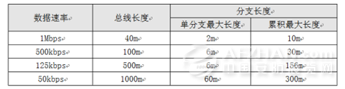
Most common CAN isolation modules have explicit overtime protection, the module's minimum baud rate is limited to 40kbps, and the module's maximum network communication distance should be 1km. After the maximum baud rate of the bus communication is determined, the bus length and branch length of the network should not exceed the limit of Table 1.
Table 1 Network lengths at different baud rates
For common application networking, refer to the recommended networking mode given in the data sheet of the CTM series isolated transceivers, that is, use single-layer shielded twisted pair cables. The following shows a reference networking method using double-shielded twisted pair cables. This method is a three-wire transmission method with the best transmission and anti-jamming performance. During the networking, the outer shield of the twisted pair is connected to the earth, and the inner shield and the twisted pair are connected to the CANG, CANH, and CANL of each transceiver. The CANG of each CAN node is connected to the chassis through a 1000pF capacitor.
Figure 6 Three-wire transmission network
Auto Engine Valves
Car Engine Valve,Auto Engine Valves,Car Valve,Auto Valves
KINCON POWER TECHNOLOGY CO.,LTD , https://www.kinconparts.com